Now you change the parent seed sheet metal part thickness.
Change global sheet metal thickness solidworks.
When cleared the body is consumed by the convert to sheet metal feature.
You can edit the global variable by double clicking the dimensions and using the modify dialog box or by editing the values in the equations dialog box.
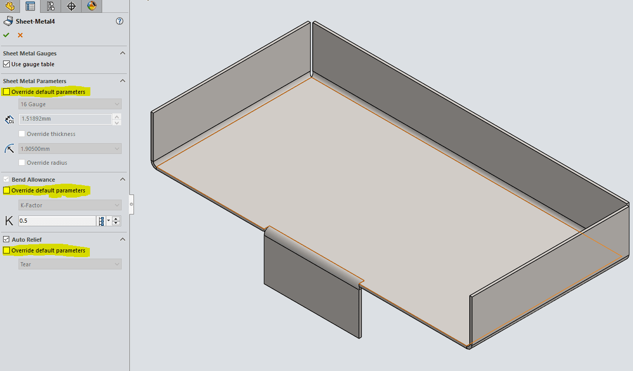
Under sheet metal parameters.
Change and manage than linked values.
This same tool can be used to make a flat piece of sheet metal that one would use to add edge flanges and other useful sheet metal features.
Changing global variables with the modify dialog box.
Solidworks 2016 sp05 to disable web help from within solidworks and use local help instead click help use.
Set the sheet thickness and default bend radius.
At this point you add another body to the mirrored part.
Set two or more dimensions equal to the global variable.
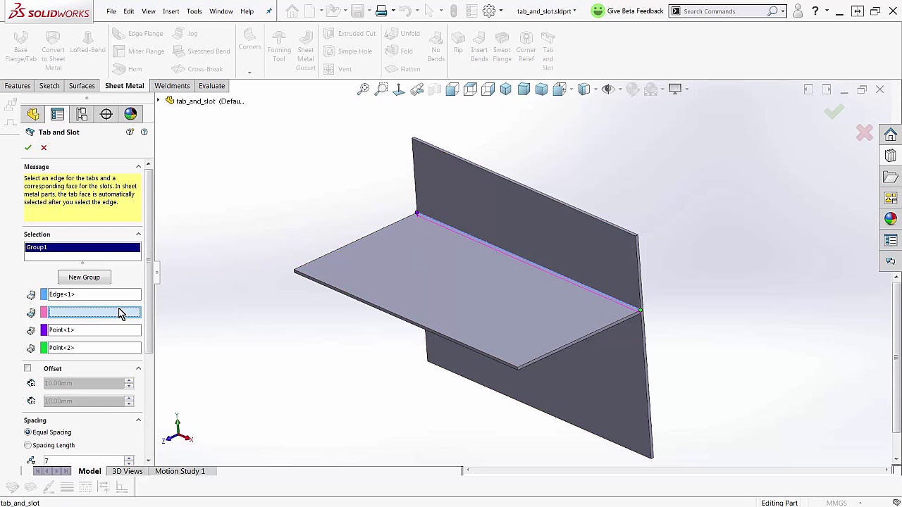
Edge flange see figure 3 can be used to add an attached wall to any sheet metal body.
Notice the override default parameter is unchecked.
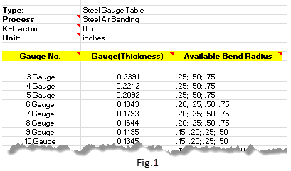
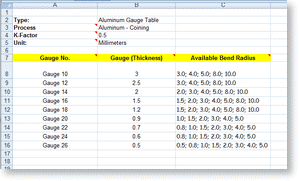
In this tech tip learn how to convert the thickness value into a solidworks sheet metal gauge value.
Notice the mirrored part thickness and global thickness variable does not.
But it doesn t appear possible to change the sheet metal thickness of a part started with base flange after the fact.
To use a global variable to link dimensions.
A common practice in industry when working with solidworks sheet metal is to show thickness as gauge value.
Select keep body if you want to keep the solid body to use in another convert to sheet metal feature.
To change dimensions linked to global variables using the modify dialog box.
Create a global variable in the equations dialog box or the modify dialog box for dimensions.
Therefore the new body will have the mirrored sheet metal part thickness at 2 mm fig.
I started out with a box with 06 thickness but as the design has evolved the box is much bigger now and i want to change its thickness to 09 but the thickness value is disabled grayed out in the sheet metal feature now.
Global variables are bi directional meaning that if two or more dimensions are defined in terms of a global variable then changing any one of the dimensions will cause the others to change.
Options in basic sheet metal base flange tab.
When you change the value of a global.